6 Things About CNC Rotary Table You May Not Have Known
CNC Rotary tables are generally ordinarily mounted "level", with the table turning around an upward hub, in a similar plane as the shape of an upward processing machine. A substitute arrangement is to mount the rotational table on its end (or mount it "level" on a 90° point plate), with the goal that it turns into an event hub. In this setup a tailstock can likewise be utilized, hence holding the workpiece "between focuses."
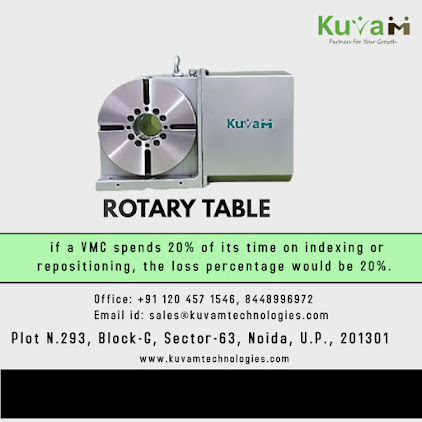
CNC Rotary Table are a type of work positioning device that is used in CNC machining centers. They are used to precisely position components at the desired angle to do multi-face operations in a single setup.
Rotary tables can be interpolated as the 4th Axis Rotary table For VMC with machines X, Y, and Z axes to enable machining of profiles such as cam machining, blade machining, and helical grooves - which would be otherwise out of reach with a standard 3 axes machining center. The table must be able to accommodate the workpiece and provide enough support to ensure precision and accuracy.
When selecting a rotary table, there are a few guidelines to keep in mind.
First, consider the size of the component you need to work with.
Second, check for the amount of swing required.
Third, check the center height of the table.
Fourth, for a multi-spindle table, check the center distance between the spindles.
Finally, in vertical conditions, if the length of the component is more than 100 mm, it is recommended to use a tailstock support.
When selecting a rotary table, you must take into consideration the clamping torque required for the operation.
To do this, you must first determine the machining forces required and the distance from the center where the operation will take place.
Then, calculate the torque that will be applied during machining (Torque = Force x Distance).
The machining torque should be within the Clamp torque capacity of the Table. Finally, you must check for the type of clamping required (Hydraulic or Pneumatic).
Select the component and fixture based on weight.
The weight should be within the capacity of the rotary table.
With tail stock, the support load capacity of the rotary table in vertical conditions will become equal to the horizontal load capacity.
To achieve the required accuracy, you need to check the indexing accuracy of the component and convert it to mm at the diameter where the operation is to be carried out.
NOTE: Higher accuracy of +/- 5” can be achieved by using an additional high-resolution encoder mounted on the table axis.
When choosing a machine, you should take into account its capacity and the size of the area in which it can operate.
You should also make sure that the machine will be able to handle the weight of the rotary table and any additional equipment.
The selection of the most suitable machine guard is based on the avoidance of fouling with the rotary table or sheet guard.
Following the mounting of the latter on the machine bed, it is essential to check for any fouling of the guard with the machine guard.
If fouling occurs, then the rear motor-mounting table can be used, provided there is sufficient space between the machine table and sheet guard when the latter is in its extreme right-hand position.
When selecting a controller, you should first check if it's capable of handling the 4th and 5th axis rotary tables for single-axis and two-axis tables respectively.
If not, we can suggest a stand-alone controller that can still perform the necessary operations even if it doesn't have continuous interpolation with the machine axes.
In some cases, controllers are only capable of 4 regular axes but the 5th axis can still do indexing.
At Kuvam Technologies Pvt Ltd, we pride ourselves on being able to provide our customers with the Direct Drive Rotary Table and its accessories that best suit their needs. If you need assistance in selecting the right product for your project, please do not hesitate to contact us at sale@kuvamtechnologies.com and we will be more than happy to help you.

%20-%20Made%20with%20PosterMyWall%20(1).jpg)
Comments
Post a Comment